README: Українська
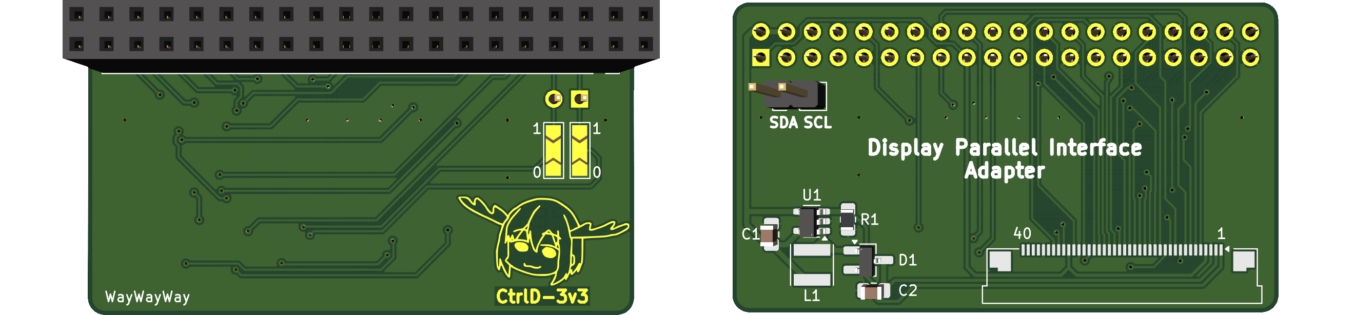
DPI4RPi is an adapter board designed to connect displays with a DPI (Display Parallel Interface) bus to the Raspberry Pi. This bus is often found in inexpensive displays, such as those from navigation devices, cameras, portable gaming consoles, etc.
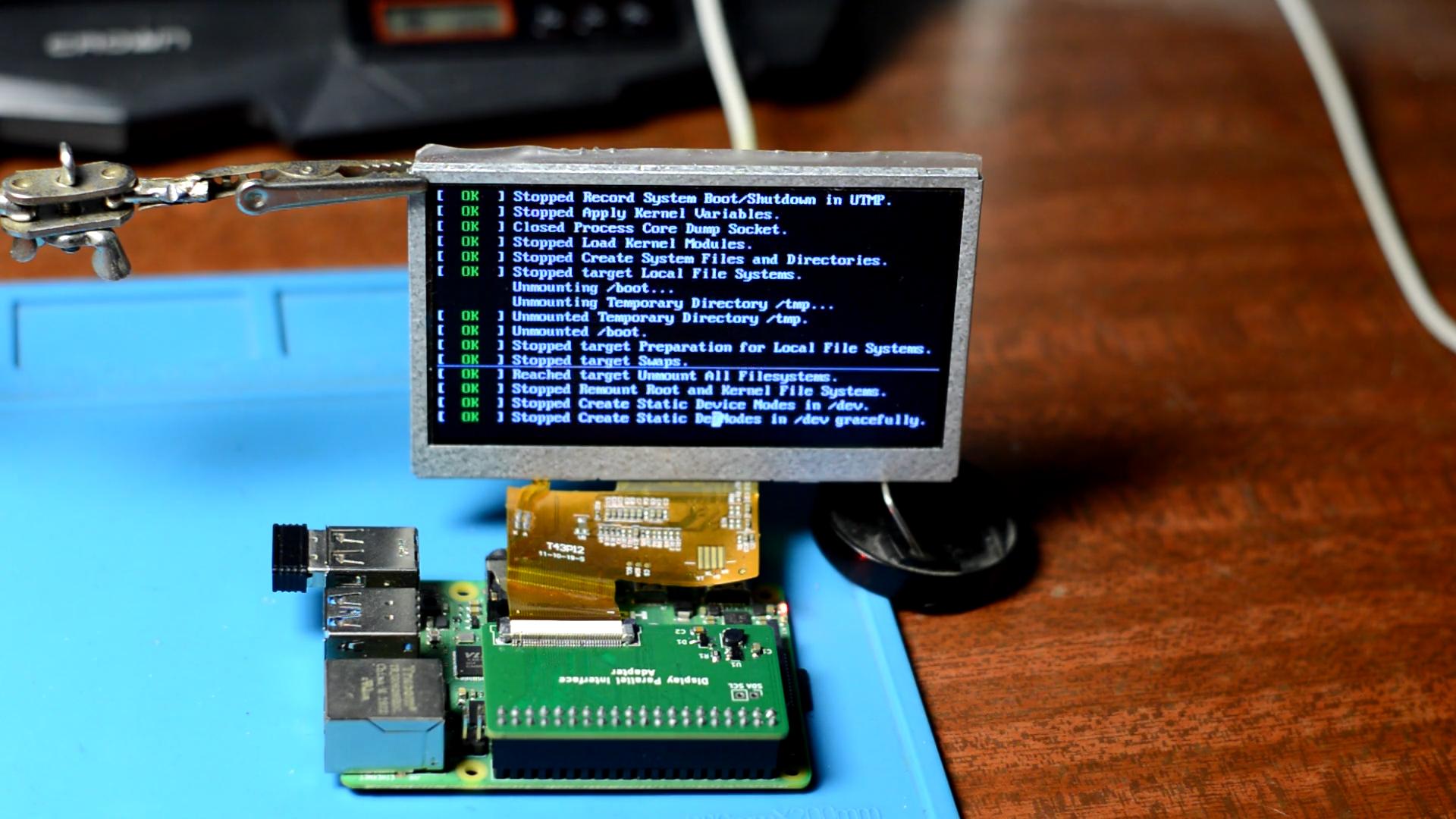
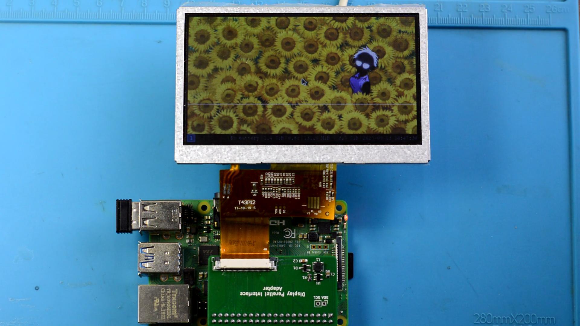
The board has been personally tested by me with the T43P12 display.
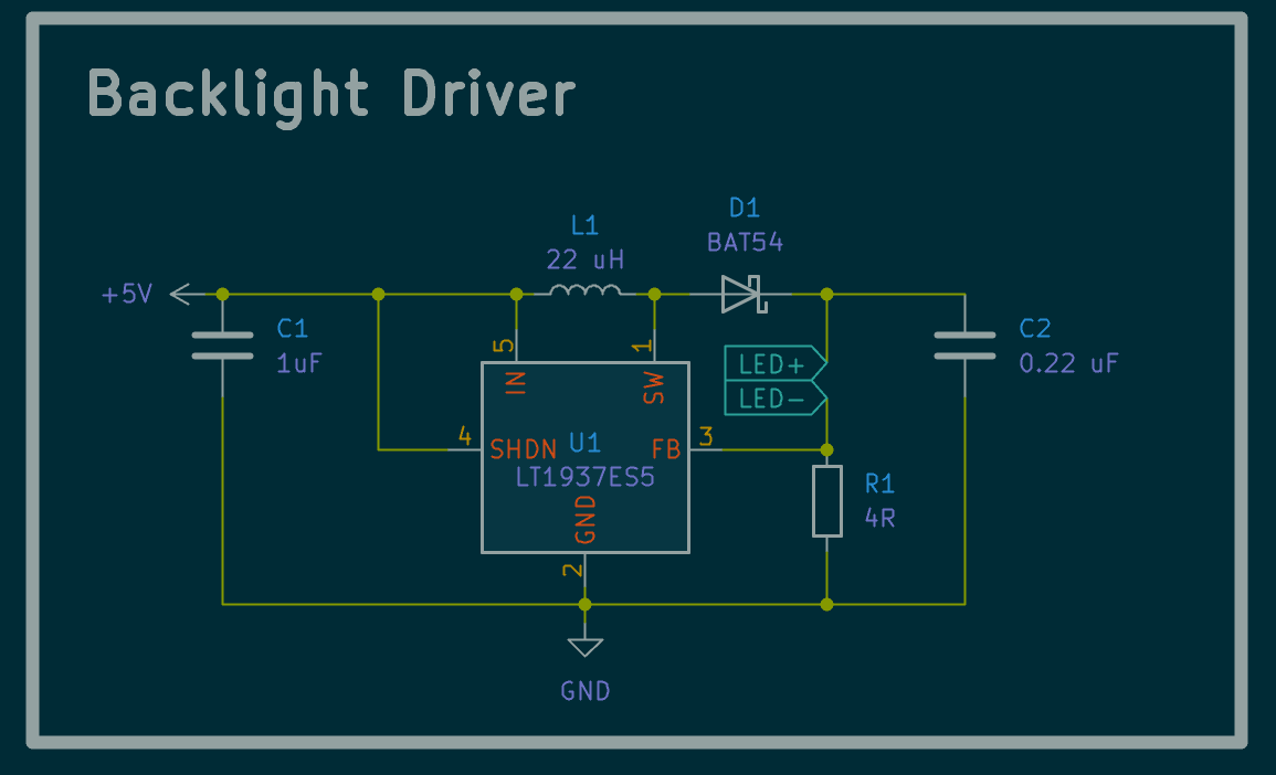
The board includes a circuit for powering the display’s backlight, with a voltage of 36V and a current of 20 mA (approximately up to 8 series connected LEDs).
WARNING: The circuit does not have an open-circuit protection, so do not connect the board without a display.
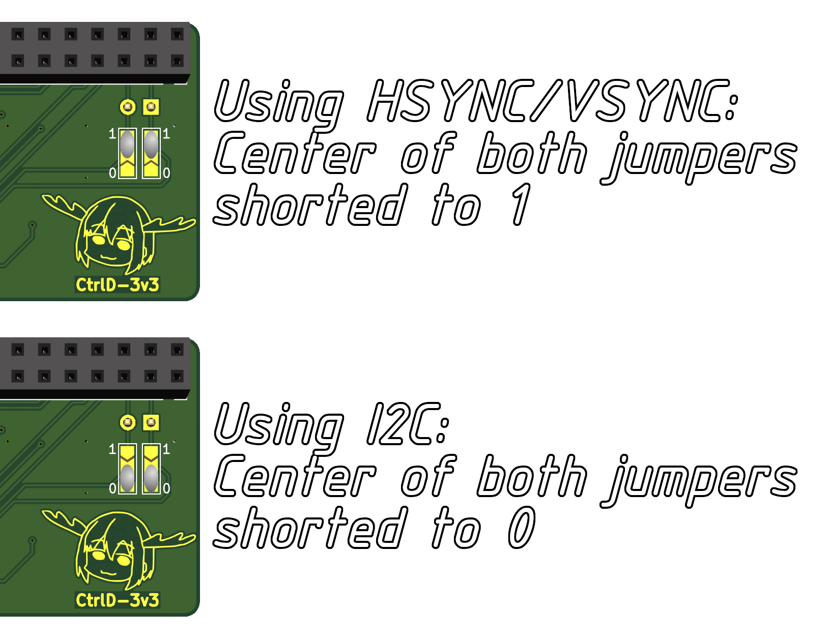
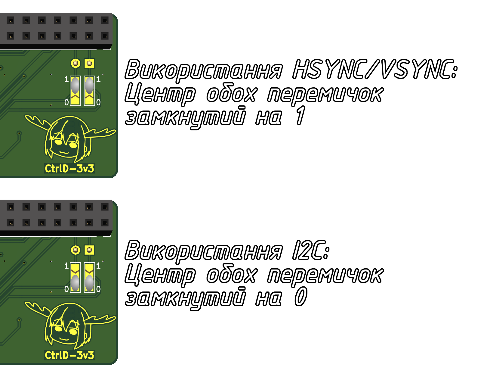
The board also features jumpers for HSYNC/VSYNC – some displays can work without them, which frees up the I2C bus. To use HSYNC and VSYNC - short both jumpers to position 1. To use I2C, short both jumpers to position 0 – this will ground the HSYNC and VSYNC, allowing the I2C to be used from the appropriate pins on the board.
- Resistors and capacitors are of 0805 package size.
- Inductor size: 4x4mm.
- Diode: BAT54 in SOT-23 package.
- Backlight power IC: LT1937ES5, in TSOT-23 package.
- Display connector: 40-pin FPC, 0.5mm pitch, contacts located ON TOP.
- Raspberry Pi connector: 2x20 pin, 2.54mm pitch.
Additionally, you will need to configure the Raspberry Pi to work with DPI. To do this, you need to edit the /boot/config.txt file. For more detailed information, you can refer to the following links: this and this.
Example of use (the board looks a little different in the photos because this is the first revision with some errors that I later fixed):
DPI4RPi це плата-адаптер, для підключення дисплеїв з шиною DPI (Display Parallel Interface) до Raspberry Pi. Така шина часто зустрічається в дешевих дисплеях, наприклад з навігаторів, камер, портативних ігрових консолей, тощо.
Плата була протестована особисто мною з дисплеєм T43P12.
На платі присутня схема для живлення підсвітки дисплея напругою 36В та струмом 20 мА (приблизно 8 послідовно з'єднаних світлодіодів).
УВАГА: схема не має захисту від розриву кола, тож не підключайте плату без дисплея.
Також на платі присутні перемички для HSYNC/VSYNC - деякі дисплеї можуть працювати без них, що дозволяє звільнити шину I2C. Щоб використовувати HSYNC та VSYNC - замкніть обидві перемички в положення 1. Щоб використовувати I2C - замкніть обидві перемички в положення 0 - це заземлить HSYNC та VSYNC, і дасть змогу використовувати I2C з відповідних контактів на платі.
- Резистори та конденсатори використані типорозміру 0805.
- Розмір дроселя: 4х4мм.
- Діод: BAT54 в корпусі SOT-23.
- Мікросхема для живлення підсвітки: LT1937ES5, в корпусі TSOT-23.
- Коннектор для дисплея: 40 pin FPC, крок 0.5мм, контакти розташовані ВГОРІ.
- Коннектор для Raspberry Pi: 2x20 pin, крок 2.54мм.
Також слід налаштувати Raspberry Pi на роботу з DPI. Для цього треба редагувати файл /boot/config.txt. Більш детально можна почитати за цим а також цим посиланнями.
Приклад використання (на фотографіях плата трішки відрізняється, бо це перша ревізія з деякими помилками, які я в подальшому виправив):